Une introduction aux PIDs
Note
For a guide on implementing PID control with WPILib, see Contrôle PID dans WPILib.
This page explains the conceptual and mathematical workings of a PID controller. A video explanation from WPI is also available.
What is a PID Controller?
The PID controller is a common feedback controller consisting of proportional, integral, and derivative terms, hence the name. This article will build up the definition of a PID controller term by term while trying to provide some intuition for how each term behaves.
First, we’ll get some nomenclature for PID controllers out of the way. In a PID context, we use the term reference or setpoint to mean the desired state of the mechanism, and the term output or process variable to refer to the measured state of the mechanism. Below are some common variable naming conventions for relevant quantities.
\(r(t)\) |
\(u(t)\) |
||
\(e(t)\) |
\(y(t)\) |
The error \(e(t)\) is the difference between the reference and the output, \(r(t) - y(t)\).
For those already familiar with PID control, this interpretation may not be consistent with the classical explanation of the P, I, and D terms corresponding to response to « past », « present », and « future » errors. While that model has merit, we will instead be approaching PID control from the viewpoint of modern control theory, as proportional controllers applied to different physical quantities we care about. This will provide a more complete explanation of the derivative term’s behavior for constant and moving setpoints.
Roughly speaking: the proportional term drives the position error to zero, the derivative term drives the velocity error to zero, and the integral term drives the total accumulated error-over-time to zero. All three terms are added together to produce the control signal. We’ll go into more detail on each of these below.
Note
Throughout the WPILib documentation, you’ll see two ways of writing the tunable constants of the PID controller.
For example, for the proportional gain:
\(K_p\) is the standard math-equation-focused way to notate the constant.
kPis a common way to see it written as a variable in software.
Despite the differences in capitalization, the two formats refer to the same concept.
Paramètre P, ou Proportionnel
The Proportional term attempts to drive the position error to zero by contributing to the control signal proportionally to the current position error. Intuitively, this tries to move the output towards the reference.
où \(K_p\) est le gain proportionnel et \(e(t)\) est l’erreur au moment actuel \(t\).
La figure ci-dessous montre un schéma-bloc pour un Système contrôlé seulement par le paramètre P.

Les gains proportionnels agissent comme des « ressorts définis par logiciel » qui tirent le Système vers la position souhaitée. Les cours de Physique nous ont appris que nous modélisons les ressorts comme \(F = - kx\) où \(F\) est la force appliquée, \(k\) est une constante proportionnelle, et \(x\) est le déplacement à partir du point d’équilibre. Cela peut s’écrire d’une autre manière \(F = k (0-x)\) où \(0\) est le point d’équilibre. Si nous redéfinissons le point d’équilibre comme le Point de consigne de notre contrôleur à rétroaction, les équations correspondent terme pour terme.
de sorte que la « force » avec laquelle le contrôleur proportionnel tire la Sortie du Système vers le Point de consigne est proportionnelle à l” Erreur, tout comme un ressort.
Paramètre D, ou dérivée
The Derivative term attempts to drive the derivative of the error to zero by contributing to the control signal proportionally to the derivative of the error. Intuitively, this tries to make the output move at the same rate as the reference.
où \(K_p\) est le gain proportionnel, \(K_d\) est le gain dérivé, et \(e (t)\) est l’erreur au moment actuelle \(t\).
La figure ci-dessous montre un schéma-bloc pour un Système contrôlé par un contrôleur PD.
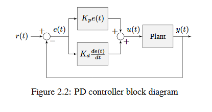
Un contrôleur PD a un contrôleur proportionnel pour la position (\(K_p\)) ET un contrôleur proportionnel pour la vitesse (\(K_d\)). Le Point de consigne de la vitesse est implicitement défini par la façon dont le Point de consigne de la position change avec le temps. Pour le prouver, nous allons reformuler l’équation pour un contrôleur PD.
where \(u_k\) is the control effort at timestep \(k\) and \(e_k\) is the error at timestep \(k\). \(e_k\) is defined as \(e_k = r_k - x_k\) where \(r_k\) is the setpoint and \(x_k\) is the current state at timestep \(k\).
Remarquez comment \(\frac {r_k - r_ {k-1}} {dt}\) est la vitesse du Point de consigne. Pour la même raison, \(\frac {x_k - x_ {k-1}} {dt}\) est la vitesse Système à un moment donné. Cela signifie que le terme \(K_d\) du contrôleur PD force la vitesse estimée vers la vitesse du Point de consigne.
Si le Point de consigne est constant, le Point de consigne vitesse est nécessairement zéro. Par conséquent, le terme \(K_d\) ralentit le Système, s’il est en déplacement. Ceci agit comme un « amortisseur défini par logiciel ». On retrouve ces amortisseurs sur certaines portes industrielles, et ils sont utilisés pour qu’elles se ferment doucement. Leur force augmente linéairement avec la vitesse.
Paramètre I, ou Intégrale
Important
Integral gain is generally not recommended for FRC® use. It is almost always better to use a feedforward controller to eliminate steady-state error. If you do employ integral gain, it is crucial to provide some protection against integral windup.
The Integral term attempts to drive the total accumulated error to zero by contributing to the control signal proportionally to the sum of all past errors. Intuitively, this tries to drive the average of all past output values towards the average of all past reference values.
où \(K_p\) est le gain proportionnel, \(K_i\) est le gain intégral, \(e (t)\) est l’erreur au moment donné \(t\), et \(\tau\) est la variable d’intégration.
L’intégrale intègre de l’instant \(0\) à l’instant actuel \(t\). Nous utilisons \(\tau\) pour l’intégration parce que nous avons besoin d’une variable pour prendre plusieurs valeurs dans l’intégrale, mais nous ne pouvons pas utiliser \(t\) parce que nous l’avons déjà défini comme l’instant actuel.
La figure ci-dessous montre un schéma-bloc pour un Système contrôlé par un contrôleur PI.
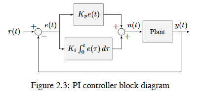
Lorsque le Système s’approche du Point de consigne en régime permanent, le terme proportionnel peut être trop petit pour faire converger la Sortie jusqu’au Point de consigne, et le terme dérivé est alors à zéro. Cela peut entraîner une erreur de régime permanent comme le montre la figure 2.4
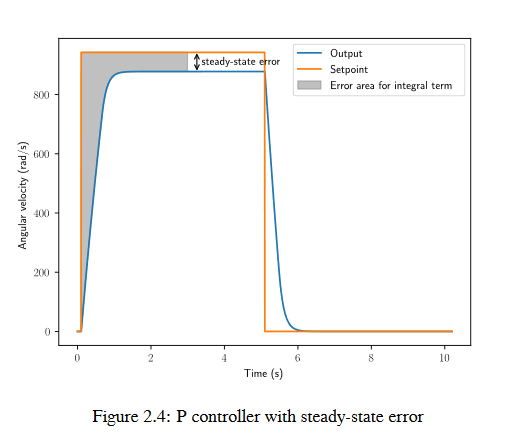
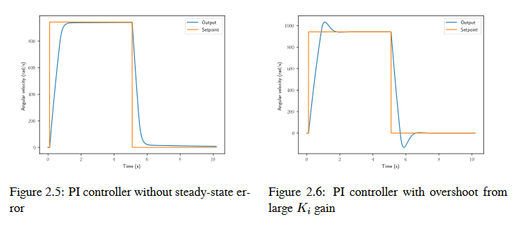
A common way of eliminating steady-state error is to integrate the error and add it to the control effort. This increases the control effort until the system converges. Figure 2.4 shows an example of steady-state error for a flywheel, and figure 2.5 shows how an integrator added to the flywheel controller eliminates it. However, too high of an integral gain can lead to overshoot, as shown in figure 2.6.
Putting It All Together
Note
Pour plus d’informations sur l’utilisation du PIDController fourni par WPILib, voir relevant article.
When these terms are combined by summing them all together, one gets the typical definition for a PID controller.
où \(K_p\) est le gain proportionnel, \(K_i\) est le gain intégral, \(K_d\) est le gain dérivé, \(e(t)\) est l’erreur au moment actuel \(t\), et \(\tau\) est la variable d’intégration.
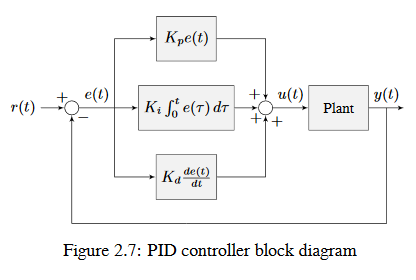
La figure ci-dessous montre un schéma-bloc d’un contrôleur PID.
Types de réponse
Un Système piloté par un contrôleur PID a généralement trois types de réponses: sous-amorti, sur-amorti et critique. Ces réponses sont illustrées à la figure 2.8.
Pour la Réponse à une transition de la figure 2.7, Temps de montée est le temps que le Système prend pour atteindre initialement la référence après avoir appliqué une impulsion d’entrée. Le Temps de destabilisation est le temps que prend le Système pour atteindre la Référence après l’application d’une impulsion d’entrée.
Une réponse sous-amortie oscille autour de la Référence avant de se stabiliser. Une réponse sur-amortie
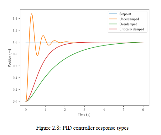
est lente à augmenter et ne dépasse pas le Référence. Une réponse amortie de manière critique a le temps de montée le plus rapide, sans toutefois dépasser la Référence.