Introducción a PID
Nota
For a guide on implementing PID control with WPILib, see Control PID en WPILib.
This page explains the conceptual and mathematical workings of a PID controller. A video explanation from WPI is also available.
What is a PID Controller?
The PID controller is a common feedback controller consisting of proportional, integral, and derivative terms, hence the name. This article will build up the definition of a PID controller term by term while trying to provide some intuition for how each term behaves.
First, we’ll get some nomenclature for PID controllers out of the way. In a PID context, we use the term reference or setpoint to mean the desired state of the mechanism, and the term output or process variable to refer to the measured state of the mechanism. Below are some common variable naming conventions for relevant quantities.
\(r(t)\) |
\(u(t)\) |
||
\(e(t)\) |
\(y(t)\) |
The error \(e(t)\) is the difference between the reference and the output, \(r(t) - y(t)\).
For those already familiar with PID control, this interpretation may not be consistent with the classical explanation of the P, I, and D terms corresponding to response to «past», «present», and «future» errors. While that model has merit, we will instead be approaching PID control from the viewpoint of modern control theory, as proportional controllers applied to different physical quantities we care about. This will provide a more complete explanation of the derivative term’s behavior for constant and moving setpoints.
Roughly speaking: the proportional term drives the position error to zero, the derivative term drives the velocity error to zero, and the integral term drives the total accumulated error-over-time to zero. All three terms are added together to produce the control signal. We’ll go into more detail on each of these below.
Nota
Throughout the WPILib documentation, you’ll see two ways of writing the tunable constants of the PID controller.
For example, for the proportional gain:
\(K_p\) is the standard math-equation-focused way to notate the constant.
kPis a common way to see it written as a variable in software.
Despite the differences in capitalization, the two formats refer to the same concept.
Término Proporcional
The Proportional term attempts to drive the position error to zero by contributing to the control signal proportionally to the current position error. Intuitively, this tries to move the output towards the reference.
donde \(K_p\) es la ganancia proporcional y \(e(t)\) es el error en tiempo actual \(t\).
La imagen a continuación muestra un diagrama de bloques para un system controlado por un controlador P.

La ganancia proporcional actúa como “un resorte definido por programa” que jala el system a la posición deseada. Recordando de la física donde modelamos resortes como \(F = - kx\) donde \(F\) es la fuerza aplicada, \(k\) es la constante proporcional y \(x\) es el desplazamiento del punto de equilibrio. Esto puede ser escrito de otra manera \(F = k(0-x)\) donde \(0\) es el punto de equilibrio. Si permitimos que el punto de equilibrio sea nuestro punto de referencia de la retroalimentación del controlador, la ecuación correspondería uno a uno.
entonces la “fuerza” con la cual el controlador proporcional jala la salida del system’s hacia la referencia es proporcional al error, así como un resorte.
Término Derivativo
The Derivative term attempts to drive the derivative of the error to zero by contributing to the control signal proportionally to the derivative of the error. Intuitively, this tries to make the output move at the same rate as the reference.
Donde \(K_p\) es la ganancia proporcional, \(K_d\) es la ganancia derivativa y \(e(t)\) es el error en el tiempo actual \(t\).
La figura a continuación muestra un diagrama de bloques para un sistema controlado por un controlador PD.
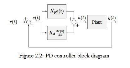
Un controlador PD tiene un controlador proporcional para la posición (\(K_p\)) y un controlador proporcional para la velocidad (\(K_d\)). El punto de referencia de la velocidad es dada implícitamente conforme al cambio del punto de referencia de la posición conforme al tiempo. Para comprobar esto, reacomodaremos la ecuación para un controlador PD.
where \(u_k\) is the control effort at timestep \(k\) and \(e_k\) is the error at timestep \(k\). \(e_k\) is defined as \(e_k = r_k - x_k\) where \(r_k\) is the setpoint and \(x_k\) is the current state at timestep \(k\).
Vea como \(\frac{r_k - r_{k-1}}{dt}\) es la velocidad del punto de referencia. Por la misma razón, \(\frac{x_k - x_{k-1}}{dt}\) es la velocidad del sistema en un tiempo unitario. Esto significa que el término \(K_d\) del controlador PD lleva la velocidad estimada al punto de referencia de la velocidad.
Si el punto de referencia es una constante, el punto de referencia implícito de la velocidad es cero, entonces el término \(K_d\) ralentiza el sistema si no está variando. Esto actúa como un «amortiguador definido por programa». Estos son encontrados comúnmente en cierrapuertas y su velocidad de amortiguamiento aumenta linealmente con la velocidad.
Término Integral
Importante
Integral gain is generally not recommended for FRC® use. It is almost always better to use a feedforward controller to eliminate steady-state error. If you do employ integral gain, it is crucial to provide some protection against integral windup.
The Integral term attempts to drive the total accumulated error to zero by contributing to the control signal proportionally to the sum of all past errors. Intuitively, this tries to drive the average of all past output values towards the average of all past reference values.
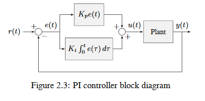
Donde \(K_p\) es la ganancia proporcional, \(K_i\) es la ganancia integral, \(e(t)\) es el error en el tiempo actual \(t\) y \(\tau\) es la integración de la variable.
La integral integra desde el tiempo \(0\) hasta el tiempo \(t\). Usamos \(\tau\) para la integración debido a que requerimos una variable que tome múltiples valores a través de la integral, pero no se podemos usar \(\t\) debido a que ya la definimos como tiempo actual.
La imagen a continuación muestra un diagrama de bloque para un sistema controlado por un controlador PI.
Cuando el sistema está cerca del punto de referencia en estado estable, el término proporcional puede ser muy pequeño para llevar la salida hasta el punto de referencia, y el término derivativo es cero. Esto pude resultar en un error de estado estable como se muestra en la figura 2.4.
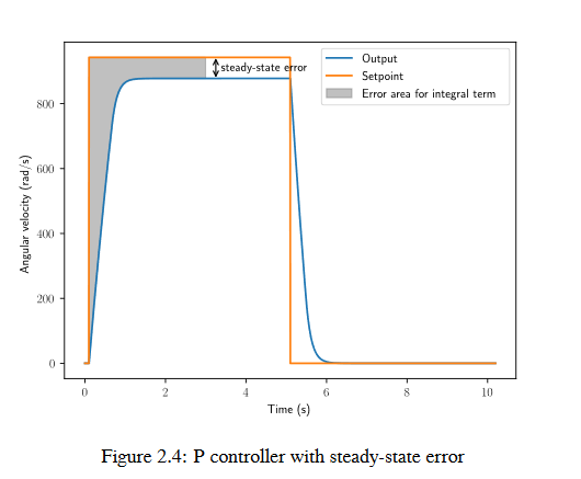
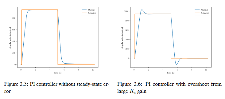
A common way of eliminating steady-state error is to integrate the error and add it to the control effort. This increases the control effort until the system converges. Figure 2.4 shows an example of steady-state error for a flywheel, and figure 2.5 shows how an integrator added to the flywheel controller eliminates it. However, too high of an integral gain can lead to overshoot, as shown in figure 2.6.
Putting It All Together
Nota
Para obtener información sobre el uso de WPILib proporcionada por PIDController, ver el artículo relevante.
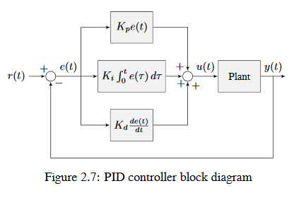
When these terms are combined by summing them all together, one gets the typical definition for a PID controller.
Donde \(K_p\) es la ganancia proporcional, \(K_i\) es la ganancia integral, \(K_d\) es la ganancia derivativa, \(e(t)\) es el error en el tiempo actual \(t\) y \(\tau\) es la variable de integración.
A continuación, se muestra un diagrama de bloques para un controlador PID.
Tipos de Respuesta
Un sistema manejado por un controlador PID generalmente tiene tres tipos de respuesta: subamortiguada, sobreamortiguada y críticamente amortiguada. Son mostradas en la figura 2.8.
En la figura 2.7 para las respuestas unitarias, el tiempo de subida es el tiempo que le toma al sistema alcanzar inicialmente la referencia después de haber aplicado la entrada unitaria. El tiempo de estabilización es el tiempo que le lleva al sistema estabilizarse en la referencia después de haber aplicado la entrada unitaria.
Una respuesta subamortiguada oscila alrededor de la referencia antes de estabilizarse. Una respuesta sobreamortiguada
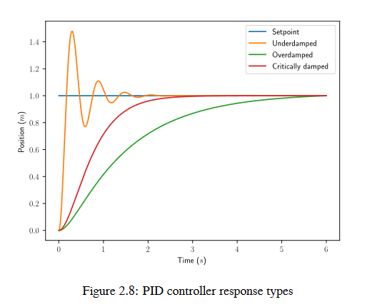
tarda en elevarse y no excede el valor de la referencia. Una respuesta críticamente amortiguada tiene el tiempo de subida más rápido sin exceder la referencia.