FRC Driver Station Powered by NI LabVIEW
Bu makale, FRC|reg| Sürücü İstasyonu NI LabVIEW tarafından desteklenmektedir.
Driver Station yazılımının yüklenmesi hakkında bilgi için bkz this document
FRC Driver Station - Sürücü İstasyonunu Başlatma
The FRC Driver Station can be launched by double-clicking the icon on the Desktop or by selecting Start->All Apps->FRC Driver Station.
Not
By default the FRC Driver Station launches the LabVIEW Dashboard. It can also be configured on Setup Tabı to launch the other Dashboards: SmartDashboard and Shuffleboard. WPILib must be installed to use SmartDashboard and Shuffleboard.
Driver Station Tuş Kısayolları
F1 - Force a Joystick refresh.
[ + ] + \ - Enable the robot (the 3 keys above Enter on most keyboards)
Enter - Disable the Robot
Space - Emergency Stop the robot. After an emergency stop is triggered the roboRIO will need to be rebooted before the robot can be enabled again.
Not
Boşluk çubuğu, Driver Station penceresinin seçili olup olmadığına bakılmaksızın robotu E-Stop yapar
Uyarı
When connected to FMS in a match, teams must press the Team Station E-Stop button to emergency stop their robot as the DS enable/disable and E-Stop key shortcuts are ignored.
Sürücü İstasyonunu Kurmak

Robotunuza bağlanmak için DS, takım numaranıza ayarlanmalıdır. Bunu yapmak için Kurulum sekmesine tıklayın ve ardından takım numarası kutusuna takım numaranızı girin. Ayarın etkili olması için return tuşuna basın veya kutunun dışını tıklayın.
PCs will typically have the correct network settings for the DS to connect to the robot already, but if not, make sure your Network adapter is set to DHCP.
Status Paneli
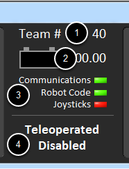
Driver Station Status Bölmesi, ekranın ortasında yer alır ve seçilen sekmeden bağımsız olarak her zaman görülebilir. DS ve robotun durumu hakkında bir dizi kritik bilgi görüntüler:
Team # - DS’nin şu anda yapılandırıldığı Takım numarası. Bu, FRC takım numaranızla eşleşmelidir. Takım numarasını değiştirmek için Setup Sekmesine bakın.
Battery Voltage - DS bağlıysa ve roboRIO ile iletişim halindeyse, bu mevcut akü voltajını bir sayı olarak ve pil simgesinde zaman içinde küçük bir voltaj çizelgesiyle görüntüler. RoboRIO karartması tetiklendiğinde sayısal göstergenin arka planı kırmızıya dönecektir. Daha fazla bilgi için RoboRIO Kesintisi ve Mevcut Çekişi Anlama a bakın.
Major Status Indicators - Bu üç gösterge, DS için ana durum öğelerini görüntüler. “Communications”, DS’nin şu anda roboRIO üzerindeki FRC Network Communications Task ile iletişim kurup kurmadığını gösterir (TCP ve UDP iletişimi için ikiye bölünmüştür). “Robot Code” göstergesi, takım Robot Kodunun şu anda çalışıp çalışmadığını gösterir (robot kodundaki Drive Station görevinin pil voltajını güncelleyip güncellemediğine göre belirlenir), “Joysticks” göstergesi en az bir kumanda çubuğunun takılı olup olmadığını gösterir ve DS tarafından tanındı.
Status String - The Status String provides an overall status message indicating the state of the robot. Some examples are “No Robot Communication”, “No Robot Code”, “Emergency Stopped”, and “Teleoperated Enabled”. When the roboRIO brownout is triggered this will display “Voltage Brownout”.
Operation Tabı

Operations Sekmesi, robotun modunu kontrol etmek ve robot çalışırken ek anahtar durum göstergeleri sağlamak için kullanılır.
Robot Mode - This section controls the Robot Mode.
Teleoperated Mode causes the robot to run the code in the Teleoperated portion of the match.
Autonomous Mode causes the robot to run the code in the Autonomous portion of the match.
Practice Mode causes the robot to cycle through the same transitions as an FRC match after the Enable button is pressed (timing for practice mode can be found on the setup tab).
Test Mode is an additional mode where test code that doesn’t run in a regular match can be tested.
Enable/Disable - These controls enable and disable the robot. See also Driver Station Key Shortcuts.
Elapsed Time - Indicates the amount of time the robot has been enabled.
PC Battery - Indicates current state of DS PC battery and whether the PC is plugged in.
PC CPU% - Indicates the CPU Utilization of the DS PC.
Window Mode - When not on the Driver account on the Classmate allows the user to toggle between floating (arrow) and docked (rectangle).
Team Station - FMS’ye bağlı olmadığında, takım istasyonunu robota aktarım yapacak şekilde ayarlar.
Not
When connected to the Field Management System the controls in sections 1 and 2 will be replaced by the words FMS Connected and the control in Section 7 will be greyed out.
Diagnostics-Arıza tespit Tabı
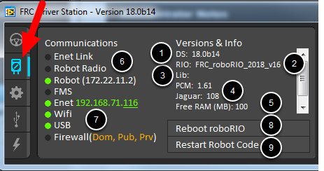
Diagnostics Sekmesi, takımların robotlarıyla ilgili sorunları teşhis etmek için kullanabilecekleri ek durum göstergeleri içerir:
DS Version - Indicates the Driver Station Version number.
roboRIO Image Version - String indicating the version of the roboRIO Image.
WPILib Version - String indicating the version of WPILib in use.
CAN Device Versions - String indicating the firmware version of devices connected to the CAN bus. These items may not be present if the CTRE Phoenix Framework has not been loaded.
Memory Stats - This section shows stats about the roboRIO memory.
Connection Indicators - Bu göstergelerin üst yarısı, çeşitli bileşenlere bağlantı durumunu gösterir.
“Enet Link”, bilgisayarın ethernet bağlantı noktasına bağlı bir şey olduğunu gösterir.
“Robot Radio”, 10.XX.YY.1’de robot kablosuz ağ köprüsüne ping durumunu gösterir.
“Robot”, mDNS kullanarak roboRIO’ya ping durumunu gösterir (statik 10.TE.AM.2 adresinin geri dönüşü ile).
“FMS”, DS’nin FMS’den paket alıp almadığını gösterir (bu bir ping göstergesi DEĞİLDİR).
Network Indicators - The second section of indicators indicates status of network adapters and firewalls. These are provided for informational purposes; communication may be established even with one or more unlit indicators in this section.
“Enet”, tespit edilen Ethernet adaptörünün IP adresini gösterir
“WiFi”, bir kablosuz adaptörün etkin olarak algılanıp algılanmadığını gösterir
“USB”, bir roboRIO USB bağlantısının tespit edilip edilmediğini gösterir
“Firewall” indicates if any firewalls are detected as enabled. Enabled firewalls will show in orange (Dom = Domain, Pub = Public, Prv = Private)
Reboot roboRIO - This button attempts to perform a remote reboot of the roboRIO (after clicking through a confirmation dialog).
Restart Robot Code - This button attempts to restart the code running on the robot (but not restart the OS).
Setup Tabı
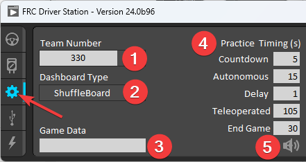
Setup Sekmesi, ekiplerin Driver Station’ın çalışmasını kontrol etmek için kullanabileceği bir dizi düğme içerir:
Team Number - Should contain your FRC Team Number. This controls the mDNS name that the DS expects the robot to be at. Shift clicking on the dropdown arrow will show all roboRIO names detected on the network for troubleshooting purposes.
Dashboard Type - Controls what Dashboard is launched by the Driver Station. Default launches the file pointed to by the “FRC DS Data Storage.ini” (for more information about setting a custom dashboard). By default this is Dashboard.exe in the Program Files (x86)\FRC Dashboard folder. LabVIEW attempts to launch a dashboard at the default location for a custom built LabVIEW dashboard, but will fall back to the default if no dashboard is found. SmartDashboard and Shuffleboard launch the respective dashboards included with the C++ and Java WPILib installation. Remote forwards LabVIEW dashboard data to the IP specified in Dashboard IP field.
Game Data - This box can be used for at home testing of the Game Data API. Text entered into this box will appear in the Game Data API on the Robot Side. When connected to FMS, this data will be populated by the field automatically.
Practice Mode Timing - Bu kutular, uygulama modu sırasının her bir kısmının zamanlamasını kontrol eder. Robot uygulama modunda etkinleştirildiğinde, DS otomatik olarak yukarıdan aşağıya gösterilen modlarda ilerler.
Audio Kontrolü - Bu düğme, practice Modu kullanıldığında ses tonlarının çıkıp çıkmayacağını kontrol eder.
USB Devices Sekmesi
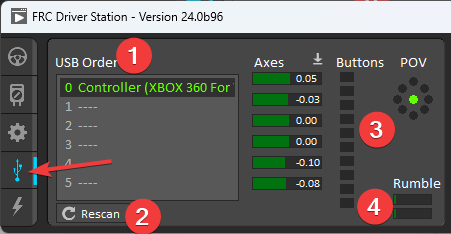
USB Devices sekmesi, DS’ye bağlı USB Aygıtları hakkındaki bilgileri içerir.
USB Setup List - Bu, DS’ye bağlı tüm uyumlu USB cihazlarının bir listesini içerir. Bir cihazda bir düğmeye basmak, adı yeşil renkte vurgular ve cihaz adının önüne 2 * lar koyar
Rescan - This button will force a Rescan of the USB devices. While the robot is disabled, the DS will automatically scan for new devices and add them to the list. To force a complete re-scan or to re-scan while the robot is Enabled (such as when connected to FMS during a match) press F1 or use this button.
Device indicators - Bu göstergeler, eksenlerin, düğmelerin ve joystick’in POV’unun mevcut durumunu gösterir.
Rumble - XInput cihazları (X-Box denetleyicileri gibi) için Rumble denetimi görünecektir. Bu, cihazın gürültü işlevselliğini test etmek için kullanılabilir. Üst çubuk “Sağ Rumble” ve alttaki çubuk “Sol Rumble” dır. Bar boyunca herhangi bir yere tıklamak ve basılı tutmak sarsıntıyı orantılı olarak etkinleştirecektir (sol sarsıntı yok = 0, sağ tam sarsıntı = 1). Bu yalnızca bir kontroldür ve robot kodunda ayarlanan Rumble değerini göstermez.
Cihazları Yeniden Düzenleme ve Kilitleme
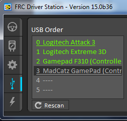
The Driver Station has the capability of “locking” a USB device into a specific slot. This is done automatically if the device is dragged to a new position and can also be triggered by double clicking on the device. “Locked” devices will show up with an underline under the device. A locked device will reserve its slot even when the device is not connected to the computer (shown as grayed out and underlined). Devices can be unlocked (and unconnected devices removed) by double clicking on the entry.
Not
If you have two or more of the same device, they should maintain their position as long as all devices remain plugged into the computer in the same ports they were locked in. If you switch the ports of two identical devices the lock should follow the port, not the device. If you re-arrange the ports (take one device and plug it into a new port instead of swapping) the behavior is not determinate (the devices may swap slots). If you unplug one or more of the set of devices, the positions of the others may move; they should return to the proper locked slots when all devices are reconnected.
Örnek: Yukarıdaki görüntü 4 cihazı göstermektedir:
Kilitli “Logitech Attack 3” joystick. Bu cihaz, başka bir yere sürüklenmedikçe veya kilidi açılmadıkça bu konumda kalacak
Kilitlenmemiş bir “Logitech Extreme 3D” joystick
Logitech F310 oyun kumandası olan kilidi açılmış bir “Gamepad F310 (Denetleyici)”
MadCatz Xbox 360 Kumandası olan kilitli, ancak bağlantısı kesilmiş bir “MadCatz GamePad (Denetleyici)”
Bu örnekte, Logitech Extreme 3D oyun çubuğunun çıkarılması, F310 Gamepad’in 1. yuvaya çıkmasına neden olacaktır. MadCatz Gamepad takmak (Yuva 1 ve 2’deki cihazlar çıkarılsa ve bu yuvalar boş olsa bile) Yuva 3’ü işgal edecektir.
CAN/Power Tabı
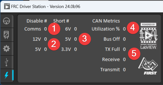
DS’nin sol tarafındaki son sekme CAN/Robot Power sekmesidir. Bu sekme roboRIO’nun güç durumu ve CAN veriyolunun durumu hakkında bilgiler içerir:
Comms Faults - DS’nin bağlandığından beri meydana gelen Haberleşme arızalarının sayısını gösterir
12V Faults - DS’nin bağlanmasından bu yana meydana gelen giriş gücü arızalarının (Brownouts) sayısını gösterir.
6V/5V/3.3V Faults - Indicates the number of faults (typically caused by short circuits) that have occurred on the User Voltage Rails since the DS has been connected
CAN Bus Utilization - CAN veriyolunun kullanım yüzdesini gösterir
CAN faults - DS bağlandığından beri 4 tip CAN arızasının her birinin sayısını gösterir.
Bir arıza tespit edilirse, bu sekmenin göstergesi (yukarıdaki resimde mavi ile gösterilmiştir) kırmızıya dönecektir.
Messages Tabı
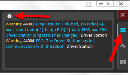
The Messages tab displays diagnostic messages from the DS, WPILib, User Code, and/or the roboRIO.
To access settings for the Messages tab, click the Gear icon. This will display a menu that will allow you to clear the box, launch a larger Console window for viewing messages, launch the DS Log Viewer, launch a viewer for program timing, or download log files from the robot.
Charts Sekmesi
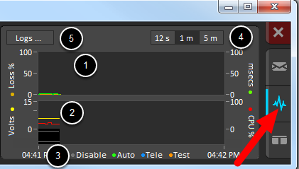
Charts sekmesi, takımların robot sorunlarını teşhis etmesine yardımcı olmak için robot durumunun gelişmiş göstergelerini çizer ve görüntüler:
The top graph charts trip time in milliseconds in green (against the axis on the right) and lost packets per second in orange (against the axis on the left).
Alt grafikte pil voltajı sarı renkte (soldaki eksene karşı), roboRIO CPU kırmızı renkte (sağdaki eksene karşı), DS Requested modu grafiğin altında sürekli bir çizgi olarak ve onubn üzerinde robot modunu kesintili bir çizgi olarak gösterir.
Bu anahtar, alttaki grafikte DS Requested ve Robot Reported modları için kullanılan renkleri gösterir.
Chart scale - These controls change the time scale of the DS Charts.
This button launches the DS Log File Viewer.
DS Requested , Drive Station’ın robota giriş için komut verdiği moddur. Robot Reported modu, her dil için kodlama çerçevelerinde bulunan raporlama yöntemlerine göre gerçekte kodun çalıştırıldığı moddur.
Her İki Sekme
The last tab on the right side is the Both tab which displays Messages and Charts side by side.