Romi Robotunu tanımak
Yön Konvansiyonları
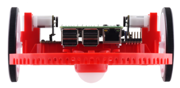
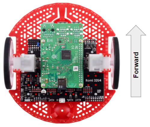
Romi’nin önü, Raspberry Pi USB bağlantı noktalarının, GPIO pinlerinin ve suspended caster tekerleğinin bulunduğu yerdir.

Tüm Romi belgelerinde, ileriye doğru ilerlemeye yönelik referanslar yukarıdaki “front” tanımını kullanır.

Hardware, Sensors, and GPIO
Romi robotu, aşağıdaki yerleşik donanıma / çevre birimlerine sahiptir:
Enkoderli 2x dişli motor
1x Atalet Ölçüm Birimi (IMU)
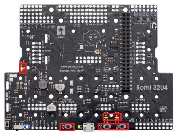
3x LED (yeşil, sarı, kırmızı)
3x buton (A, B ve C olarak işaretlenmiştir)
5x configurable GPIO channels (EXT)
Buzzer
Not
The Buzzer is currently not supported by WPILib.
Motors, Wheels, and Encoders
Romi robotunda kullanılan motorlar 120: 1 dişli redüksiyonuna ve 4,5V’de 150 RPM yüksüz çıkış hızına sahiptir. Serbest akım 0,13 amperdir ve durma akımı 1,25 amperdir. Durma torku 25 oz-inçtir (0.1765 N-m), ancak yerleşik emniyet kavraması daha düşük torklarda kaymaya başlayabilir.
Tekerlekler 70 mm (2,75 “) çapa sahiptir ve 141 mm (5,55”) iz genişliğine sahiptirler.
Enkoderlar doğrudan motor çıkış şaftına bağlanır ve 12 Devir Başına Sayıma (CPR) sahiptir. Sağlanan dişli oranıyla, bu, tekerlek dönüşü başına 1440 sayım yapar.
The motor PWM channels are listed in the table below.
Channel |
Romi Donanım Bileşeni |
|---|---|
PWM 0 |
Left Motor |
PWM 1 |
Right Motor |
Not
The right motor will spin in a backward direction when positive output is applied. Thus, the corresponding motor controller needs to be inverted in robot code.
The encoder channels are listed in the table below.
Channel |
Romi Donanım Bileşeni |
|---|---|
DIO 4 |
Sol Kodlayıcı Dörtlü Kanal A |
DIO 5 |
Sol Enkoder Dörtlü Kanal B |
DIO 6 |
Sağ Kodlayıcı Dörtlü Kanal A |
DIO 7 |
Sağ Kodlayıcı Dörtlü Kanal B |
Not
Varsayılan olarak, kodlayıcılar Romi ileri gittiğinde sayar.
Atalet ölçü birimi
Romi robotu, 3 eksenli cayro ve 3 eksenli ivmeölçer içeren bir STMicroelectronics LSM6DS33 Atalet Ölçüm Birimi (IMU) içerir.
The accelerometer has selectable sensitivity of 2G, 4G, 8G, and 16G. The gyro has selectable sensitivity of 125 Degrees Per Second (DPS), 250 DPS, 500 DPS, 1000 DPS, and 2000 DPS.
Romi robotu web kullanıcı arayüzü ayrıca, robot koduyla kullanılmadan önce jiroskopu kalibre etmek ve sıfır ofsetlerini ölçmek için bir araç sağlar.
Configurable GPIO Pins
The control board has 5 configurable GPIO pins (named EXT0 through EXT4) that allow a user to connect external sensors and actuators to the Romi.

All 5 pins support the following modes: Digital IO, Analog In, and PWM (with the exception of EXT 0, which only supports Digital IO and PWM). The mode of the ports can be configured with The Romi Web UI.
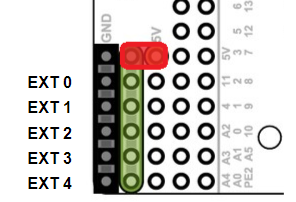
GPIO kanalları, Topraklama, Güç ve Sinyal bağlantılarıyla (Toprak bağlantısı kartın kenarına en yakın ve sinyal kartın içine en yakın olacak şekilde) 3 pimli, servo tarzı bir arabirim aracılığıyla gösterilir.
The power connections for the GPIO pins are initially left unconnected but can be hooked into the Romi’s on-board 5V supply by using a jumper to connect the 5V pin to the power bus (as seen in the image above). Additionally, if more power than the Romi can provide is needed, the user can provide their own 5V power supply and connect it directly to power bus and ground pins.
GPIO Default Configuration
The table below shows the default configuration of the GPIO pins (EXT0 through EXT4). The Romi Web UI allows the user to customize the functions of the 5 configurable GPIO pins. The UI will also provide the appropriate WPILib channel/device mappings on screen once the IO configuration is complete.
Channel |
Ext Pin |
|---|---|
DIO 8 |
EXT0 |
Analog In 0 |
EXT1 |
Analog In 1 |
EXT2 |
PWM 2 |
EXT3 |
PWM 3 |
EXT4 |
