roboRIO掉电处理以及了解电能消耗
为了在高电流消耗期间帮助维持电池电压以保护其自身和其他控制系统组件(例如在高电流事件中保护无线电设备),roboRIO包含分阶段的掉电保护方案。本文介绍了此方案,提供了有关主动计划的系统电流消耗的信息,并介绍了如何使用PDP和DS Log File Viewer的新功能去了解掉电事件,如果它们真的发生在您的机器人上的话。
roboRIO掉电保护
roboRIO使用分阶段的掉电保护方案来尝试稳定自身和其他控制系统组件的输入电压,以防止在大电流消耗的情况下,电池电压拉的过低而导致设备复位。
阶段1 - 6v输出下降
触发电压 - 6.8V
When the voltage drops below 6.8V, the 6V output on the PWM pins will start to drop.
阶段2 - 输出禁用
触发电压 - 6.3V
当电压降至6.3V以下时,控制器将进入掉电保护状态。当进入该状态时,会有下列指示:
roboRIO上的电源LED指示灯将变为琥珀色
Driver Station上的电压显示背景将变为红色
Driver Station上的显示模式将转变为“电压不足”
DS的CAN / Power选项卡会将12V故障计数器加1。
DS将在DS日志中记录一次掉电事件。
控制器将采取以下步骤来尝试保持电池电压:
PWM输出将被禁用。对于已设置中性值的PWM输出(WPILib中的所有电机控制器),在禁用输出之前,将发送一个中性脉冲。
禁用6V,5V,3.3V用户轨(包括PWM引脚上的6V输出,DIO连接器组中的5V引脚,模拟组中的5V引脚,SPI和I2C组中的3.3V引脚以及MXP bank中的5V和3.3V引脚)
配置为输出的GPIO进入High-Z模式
继电器输出被禁用(设为低电平)
向基于CAN的电机控制器发送明确的禁用指令
Pneumatic Devices such as the CTRE Pneumatics Control Module and REV Pneumatic Hub are disabled
控制器将保持此状态,直到电压上升至大于7.5V或降至触发下一阶段的掉电的电压
阶段3-装置停电
**触发电压 - 4.5V **
低于4.5V时,设备可能会停电。确切的停电电压可能低于此电压,这取决于设备的负载。
控制器将保持断电状态,直到电压升高到4.65V以上。这时设备将按正常顺序启动。
避免掉电 - 主动规划电流使用

避免掉电的关键是主动规划机器人的电流消耗。最好的方法是创建某种形式的功率预算。这种预算可能是相当复杂的时间和对应的预计电流消耗的量化,以便在比赛结束时全面了解电流使用情况和电池状态;也可以是简单地关于电流使用的清单。为创建功率预算:
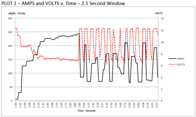
制定最大的“持续”电流消耗(此处将“持续”宽松地定义为非瞬时的)。这可能是创建功耗预算中最困难的部分。维持7+伏特电压时,电池可以维持的确切电流取决于多种因素,例如电池的健康状况(请参阅用于测量电池的健康状况的此<docs/hardware/hardware-basics/robot-battery:Robot Battery Basics>文章)和充电状态。如“ NP18-12数据表<https://www.farnell.com/datasheets/575631.pdf>” __中所示,随着充电状态的降低,尤其是电流消耗的增加,端子电压图变得非常陡峭。该数据表显示,在3CA连续负载(54A)下,全新电池可以连续运行6分钟以上,同时保持端子电压超过7V。如上图所示(在“ Team 234s驱动器系统测试”文件<https://www.chiefdelphi.com/t/paper-new-control-functions-drive-system-testing/139165>`__的允许下使用),即使使用了一块新电池,绘制240A的时间也可能超过一两秒。这为我们设定持续电流消耗提供了一些界限。出于本练习的目的,我们将限制设置为180A。
列出机器人的不同功能,例如动力传动系统,操纵器,主要游戏机制等。
Start assigning your available current to these functions. You will likely find that you run out pretty quickly. Many teams gear their drivetrain to have enough torque to slip their wheels at 40-50A of current draw per motor. If we have 4 motors on the drivetrain, that eats up most, or even exceeds, our power budget! This means that we may need to put together a few scenarios and understand what functions can (and need to be) be used at the same time. In many cases, this will mean that you really need to limit the current draw of the other functions if/while your robot is maxing out the drivetrain (such as trying to push something). Benchmarking the “driving” current requirements of a drivetrain for some of these alternative scenarios is a little more complex, as it depends on many factors such as number of motors, robot weight, gearing, and efficiency. Current numbers for other functions can be done by calculating the power required to complete the function and estimating efficiency (if the mechanism has not been designed) or by determining the torque load on the motor and using the torque-current curve to determine the current draw of the motors.
如果您在分析中确定了互斥功能,请考虑在在软件中加强体现。您还可以在机器人程序中使用PDP电流监控(下面将详细介绍)来动态设置输出限制或排除(例如,当传动系统电流超过X时不要运行机械马达,或者当传动系统电流超过Y时仅让马达半功率运行)。
Settable Brownout
The NI roboRIO 1.0 does not support custom brownout voltages. It is fixed at 6.3V as mentioned in Stage 2 above.
The NI roboRIO 2.0 adds the option for a software settable brownout level. The default brownout level (Stage 2) of the roboRIO 2.0 is 6.75V.
RobotController.setBrownoutVoltage(7.0);
frc::RobotController::SetBrownoutVoltage(7_V);
Measuring Current Draw using the PDP/PDH
The FRC® Driver Station works in conjunction with the roboRIO and PDP/PDH to extract logged data from the PDP/PDH and log it on your DS PC. A viewer for this data is still under development.
In the meantime, teams can use their robot code and manual logging, a LabVIEW front panel or the SmartDashboard to visualize current draw on their robot as mechanisms are developed. In LabVIEW, you can read the current on a PDP/PDH channel using the Get PD Currents VI found on the Power pallet. For C++ and Java teams, use the PowerDistribution class as described in the Power Distribution article. Plotting this information over time (easiest with a LV Front Panel or with the SmartDashboard by using a Graph indicator can provide information to compare against and update your power budget or can locate mechanisms which do not seem to be performing as expected (due to incorrect load calculation, incorrect efficiency assumptions, or mechanism issues such as binding).
识别掉电

识别掉电的最简单方法是单击DS的CANPower选项卡,然后检查12V故障计数。或者,您可以在发现掉电后使用Driver Station Log Viewer查看Driver Station Log。该日志将用亮橙色线标识掉电情况,如上图所示(请注意,这些掉电是由台式电源引起的,可能无法反映通常发生的FRC机器人掉电的持续时间和行为)。