Kodlayıcılar-Donanım
Not
This section covers encoder hardware. For a software guide to encoders, see Encoders - Software.
Encoders are by far the most common method for measuring rotational motion in FRC®, and for good reason - they are cheap, easy-to-use, and reliable. As they produce digital signals, they are less-prone to noise and interference than analog devices (such as potentiometers).
Kodlayıcı Türleri
There are three main ways encoders connect physically that are typically used in FRC:
Bu kodlayıcılar, söz konusu mekanizmaya nasıl monte edildiklerine göre değişir. Bu tür kodlayıcılara ek olarak, birçok FRC mekanizması tasarımlarına entegre edilmiş quadrature kodlayıcılarla birlikte gelir.
There are also three main ways the encoder data is communicated that are typically used in FRC:
Not
Some encoders may support more then one communication method
Shafted Encoders
Shafted encoders have a sealed body with a shaft protruding out of it that must be coupled rotationally to a mechanism. This is often done with a helical beam coupling, or, more cheaply, with a length of flexible tubing (such as surgical tubing or pneumatic tubing), fastened with cable ties and/or adhesive at either end. Many commercial off-the-shelf FRC gearboxes have purpose-built mounting points for shafted encoders.
Examples of shafted encoders:
On-shaft Encoders
On-shaft encoders couple to a shaft by fitting around it, forming a friction coupling between the shaft and a rotating hub inside the encoder.
Examples of On-shaft encoders:
AMT103-V available through FIRST Choice
Magnetic Encoders

Magnetic encoders require no mechanical coupling to the shaft at all; rather, they track the orientation of a magnet fixed to the shaft. While the no-contact nature of magnetic encoders can be handy, they often require precise construction in order to ensure that the magnet is positioned correctly with respect to the encoder.
Examples of magnetic encoders:
Quadrature Encoders
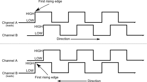
“Quadrature” terimi, hareketin ölçüldüğü/kodlandığı yöntemi ifade eder. Bir quadrature kodlayıcı, aşağıdaki resimde görüldüğü gibi, birbirinden 90 derece faz farkı olan iki kare dalga darbesi üretir:

Bu nedenle, her iki kanalda, peryod başına toplam dört “kenar” vardır (dolayısıyla “dörtlü-quad”). İki faz farklı darbenin kullanılması, hareket yönünün, hangi darbenin diğerini “yönlendirdiği” net bir şekilde belirlenmesine izin verir.
As each square wave pulse is a digital signal, quadrature encoders connect to the digital input ports on the roboRIO.
Examples of quadrature encoders:
AMT103-V available through FIRST Choice
Quadrature Encoder Wiring
Quadrature Encoders, such as the E4T OEM Miniature Optical Encoder, can be wired to two digital input ports as shown above.
Index
Some quadrature encoders have a third index pin which pulses when the encoder completes a revolution.
Quaderature Encoder Resolution
Uyarı
“CPR”-cycles per revolution ve “PPR” kısaltmaları her ikisi de, çeşitli kaynaklarda her kenarı ve devir başına döngüyü belirtmek için kullanılır, bu nedenle kısaltma tek başına ikisinden hangisinin geçerli olduğunu belilemeye yetmez. Şüphe duyduğunuzda, kodlayıcınızın teknik kılavuzuna bakın.
Kodlayıcılar dönüşü dijital darbelerle ölçtüğü için, ölçümün doğruluğu, belirli bir dönme hareketi miktarı başına darbe sayısı ile sınırlıdır. Bu, kodlayıcının “çözünürlüğü” olarak bilinir ve geleneksel olarak iki farklı yoldan biriyle ölçülür: devir başına kenar veya devir başına döngü.
Devir başına kenarlar, kodlayıcı milinin her iki kanalında da yüksekten düşüğe veya düşükten yükseğe geçişlerin toplam sayısını ifade eder. Tam bir nokta dört kenar içerir.
Devir başına döngü, enkoder milinin dönüşü başına her iki kanalın toplam tam dönem sayısını ifade eder. Tam bir peryod bir döngüdür.
Bu nedenle, devir başına kenarlarda belirtilen bir çözünürlük, devir başına döngülerde belirtilen aynı çözünürlüğün dört katı bir değere sahiptir.
Genel olarak, kodlayıcınızın dönüş başına kenardaki çözünürlüğü, konumlandırmadaki kabul edilebilir en küçük hatanızdan biraz daha hassas olmalıdır. Dolayısıyla, mekanizmayı artı veya eksi bir derece bilmek istiyorsanız, dönüş başına 360 kenardan biraz daha yüksek çözünürlüğe sahip bir kodlayıcıya sahip olmalısınız.
Duty Cycle Encoders

Duty cycle encoders connect to a single digital input on the roboRIO. They output a pulse where the length of a pulse is proportional to the absolute position of the encoder.
Examples of duty cycle encoders:
Analog Encoders
Analog encoders connect to a analog input on the roboRIO. They output a voltage proportional to the absolute position of the encoder.
Examples of analog encoders: