Analog Potentiometers - Hardware
Note
This section covers analog potentiometer hardware. For a software guide to analog potentiometers, see Analog Potentiometers - Software.
Warning
Potentiometers generally have a mechanically-limited travel range. Users should be careful that their mechanisms do not turn their potentiometers past their maximum travel, as this will damage or destroy the potentiometer.
Apart from quadrature encoders, another common way of measuring rotation on FRC robots is with analog potentiometers. A potentiometer is simply a variable resistor - as the shaft of the potentiometer turns, the resistance changes (usually linearly). Placing this resistor in a voltage divider allows the user to easily measure the resistance by measuring the voltage across the potentiometer, which can then be used to calculate the rotational position of the shaft.
Wiring an analog potentiometer
As suggested by the names, analog potentiometers connect to the roboRIO’s analog input ports. To understand how exactly to wire potentiometers, however, it is important to understand their internal circuitry.
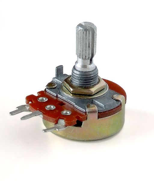

The picture above on the left shows a typical potentiometer. There are three pins, just as there are on the RIO’s analog inputs. The middle pin is the signal pin, while the outer pins can both be either power or ground.
As mentioned before, a potentiometer is a voltage divider, as shown in the circuit diagram on the right. As the potentiometer shaft turns, the resistances R1 and R2 change; however, their sum remains constant 1. Thus, the voltage across the entire potentiometer remains constant (for the roboRIO, this would be 5 volts), but the voltage between the signal pin and either the voltage or ground pin varies linearly as the shaft turns.
Since the circuit is symmetric, it is reversible - this allows the user to choose at which end of the travel the measured voltage is zero, and at which end it is 5 volts. To reverse the directionality of the sensor, it can simply be wired backwards! Be sure to check the directionality of your potentiometer with a multimeter to be sure it is in the desired orientation before soldering your wires to the contacts.
Absolute encoders
An “absolute encoder” is an encoder that measures the absolute position of the encoder shaft, rather than the incremental movement (as a quadrature encoder) does. In this respect, absolute encoders are more similar to potentiometers than to incremental encoders. Many absolute encoders offer a simple analog output - these can be used exactly in the same way as a potentiometer, except their wiring is not generally reversible. Absolute encoders have the advantage of lacking a hard travel limit - the signal will simply reset when the shaft crosses the zero point.
Absolute encoders that do not offer a simple analog output require more complicated communications with the RIO.