空间状态控制简介
备注
本文来自于`Controls Engineering in FRC|reg| <https://file.tavsys.net/control/controls-engineering-in-frc.pdf>`,已获得作者Tyler Veness的许可。
从PID到基于模型的控制
当调优PID控制器时,我们关注于摆弄与当前、过去和未来 error (P、I和D项)相关的控制器参数,而不是底层系统状态。虽然这种方法在很多情况下都有效,但它是一种不完整的世界观。
基于模型的控制重点在于开发我们试图控制的 system (机制)的精确模型。这些模型帮助反馈控制器根据系统的物理响应选择 gains 1,而不是通过测试得到的任意比例 gain。这使我们不仅能够提前预测系统的反应,而且可以在没有物理机器人的情况下测试控制器,节省调试简单bug的时间。
备注
State-space control makes extensive use of linear algebra. More on linear algebra in modern control theory, including an introduction to linear algebra and resources, can be found in Chapter 5 of Controls Engineering in FRC.
If you’ve used WPILib’s feedforward classes for SimpleMotorFeedforward or its sister classes, or used SysId to pick PID gains for you, you’re already familiar with model-based control! The kv and ka gains can be used to describe how a motor (or arm, or drivetrain) will react to voltage. We can put these constants into standard state-space notation using WPILib’s LinearSystem, something we will do in a later article.
词汇表
对于本文中使用的背景词汇,清参阅:ref:Glossary <docs/software/advanced-controls/controls-glossary:Controls Glossary>.
线性代数导论
为了简短,直观地介绍线性代数的核心概念,我们建议`3Blue1Brown线性代数系列<https://www.youtube.com/watch?v=fNk_zzaMoSs&list=PLZHQObOWTQDPD3MizzM2xVFitgF8hE_ab>`__的第1章至第4章(向量,它们甚至是什么?,线性组合,跨度和基向量,线性变换和矩阵,以及矩阵乘法作为组合)。
什么是状态空间?
Recall that 2D space has two axes: x and y. We represent locations within this space as a pair of numbers packaged in a vector, and each coordinate is a measure of how far to move along the corresponding axis. State-space is a Cartesian coordinate system with an axis for each state variable, and we represent locations within it the same way we do for 2D space: with a list of numbers in a vector. Each element in the vector corresponds to a state of the system. This example shows two example state vectors in the state-space of an elevator model with the states \([\text{position}, \text{velocity}]\):
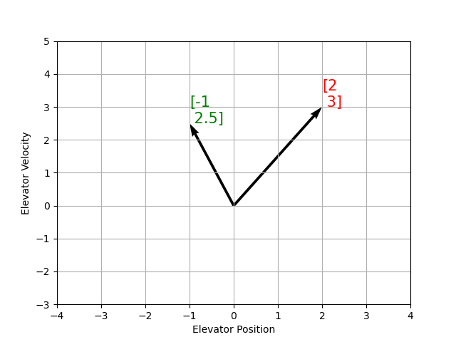
在此图像中,表示状态空间中状态的向量是箭头。从现在开始,这些向量将仅由向量尖端处的一个点表示,但请记住,向量的其余部分仍然存在。
除了 state`之外,:term:`inputs 1 and :term:`outputs 2`也被表示为向量。由于从当前状态和输入到状态变化的映射是一个方程式系统,因此很自然地以矩阵形式编写它。该矩阵方程式可以用状态空间符号表示。
什么是状态空间符号?
状态空间符号是一组矩阵方程,描述了系统随着时间的变化。这些方程将状态 \(\dot{\mathbf{x}}`和:term:`output\) \(\mathbf{y}`的变化与当前状态向量的线性组合相关联::math:\)mathbf{x}` and input vector \(\mathbf{u}\)。
状态空间控制可以处理连续时间和离散时间系统。在连续时间情况下,系统状态:math:mathbf{dot{x}}`的变化率表示为当前状态 :math:mathbf{x}` 和输入:math:`mathbf{u}`的线性组合。
相反,离散时间系统基于当前状态 \(\mathbf{x}_k`和下一个时间步表示系统状态:math:\)mathbf{x}_{k+1}`和输入:math:mathbf{u}_k,其中 \(k`是当前时间步,而:math:`k+1\) 是下一个时间步。
无论是连续时间形式还是离散时间形式, output 向量:math:mathbf{y} 都表示为当前:term:state 和 :term:`input`的线性组合。在许多情况下,输出是系统状态的子集,没有来自当前输入的贡献。
在对系统进行建模时,我们首先导出连续时间表示形式,因为运动方程很自然地写为系统状态的变化率,即系统当前状态和输入的线性组合。我们将这种表示形式转换为机器人上的离散时间,因为我们在此以离散时间步长而不是连续地更新系统。
以下两组方程式是连续时间和离散时间状态空间符号的标准形式:
连续时间状态空间系统可以通过称为离散化的过程转换为离散时间系统。
备注
在离散时间形式中,系统状态在两次更新之间保持不变。这意味着我们只能在状态估计值更新后尽快对干扰做出反应。更快地更新我们的估计值可以在一定程度上帮助改善性能。如果需要比机械手主循环更快的更新速度,则可以使用WPILib的“ Notifier”类。
备注
虽然系统的连续时间矩阵和离散时间矩阵A,B,C和D具有相同的名称,但它们并不等效。连续时间矩阵描述状态的变化率:math:mathbf{x},而离散时间矩阵描述系统在下一时间步的状态是当前状态和输入的函数。
重要
WPILib的LinearSystem采用连续时间系统矩阵,并在必要时将其内部转换为离散时间形式。
State-space Notation Example: Flywheel from Kv and Ka
Recall that we can model the motion of a flywheel connected to a brushed DC motor with the equation \(V = K_v \cdot v + K_a \cdot a\), where V is voltage output, v is the flywheel’s angular velocity and a is its angular acceleration. This equation can be rewritten as \(a = \frac{V - K_v \cdot v}{K_a}\), or \(a = \frac{-K_v}{K_a} \cdot v + \frac{1}{K_a} \cdot V\). Notice anything familiar? This equation relates the angular acceleration of the flywheel to its angular velocity and the voltage applied.
我们可以将该方程转换为状态空间符号。我们可以创建一个具有一个状态(速度),一个 input (电压)和 output`(速度)的系统。回想一下速度的一阶导数是加速度,我们可以编写如下公式,用 :math:mathbf{x}`代替速度,用 \(\mathbf{\dot{x}}`代替加速度,并且用 :math:\)mathbf{u}`代替电压:math:mathbf{V} :
The output and state are the same, so the output equation is the following:
That’s it! That’s the state-space model of a system for which we have the \(K_v\) and \(K_a\) constants. This same math is used in system identification to model flywheels and drivetrain velocity systems.
可视化状态空间响应:相位图
A phase portrait can help give a visual intuition for the response of a system in state-space. The vectors on the graph have their roots at some point \(\mathbf{x}\) in state-space, and point in the direction of \(\mathbf{\dot{x}}\), the direction that the system will evolve over time. This example shows a model of a pendulum with the states of angle and angular velocity.
要追踪系统可能会穿越状态空间的潜在轨迹,请选择一个起点并遵循周围的箭头。在此示例中,我们可能从:math:`[-2, 0]`开始。从那里开始,速度随着我们垂直摆动而增加,并开始降低,直到达到相反的极端。围绕原点旋转的循环无限期地重复。
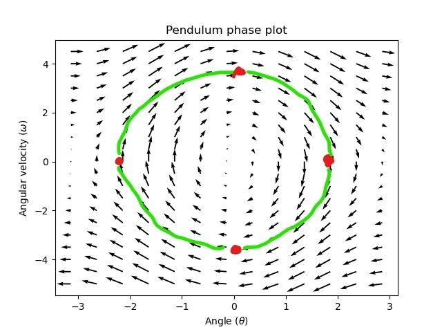
注意,在相像的边缘附近,X轴绕着:math:pi 弧度逆时针旋转,并且:math:pi 弧度顺时针旋转将在同一点结束。
有关微分方程和相画像的更多信息,请参见`3Blue1Brown’s Differential Equations video <https://www.youtube.com/watch?v=p_di4Zn4wz4>`,它们在15:30左右为摆相空间设置动画效果非常出色。
可视化前馈
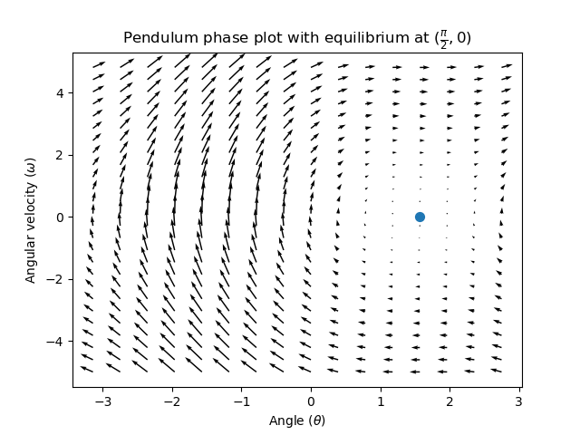
这个阶段描述显示了系统的“开环”响应——也就是说,如果我们让状态自然发展,它将如何反应。例如,如果要平衡水平摆(在状态空间中的:math:(frac{pi}{2}, 0)`处),我们将需要以某种方式应用控制:term:`input 以抵消摆向下摆动的开环趋势。这就是前馈正在尝试做的——以使我们的相位图在状态空间中的 reference 位置(或设定点)处具有平衡。
Looking at our phase portrait from before, we can see that at \((\frac{\pi}{2}, 0)\) in state space, gravity is pulling the pendulum down with some torque T, and producing some downward angular acceleration with magnitude \(\frac{\tau}{I}\), where I is angular moment of inertia of the pendulum. If we want to create an equilibrium at our reference of \((\frac{\pi}{2}, 0)\), we would need to apply an input can counteract the system’s natural tendency to swing downward. The goal here is to solve the equation \(\mathbf{0 = Ax + Bu}\) for \(\mathbf{u}\). Below is shown a phase portrait where we apply a constant input that opposes the force of gravity at \((\frac{\pi}{2}, 0)\):
反馈控制
在直流电动机的情况下,只需要一个数学模型和系统的所有当前状态(即角速度)的知识,我们就可以根据未来的电压输入预测所有未来的状态。但是,如果系统受到我们的方程所没有模拟的任何干扰,比如负载或意外摩擦,电机的角速度会随着时间的推移偏离模型。为了解决这个问题,我们可以使用反馈控制器给电机校正命令。
PID控制器是反馈控制的一种形式。状态空间控制通常使用以下控制法则,其中 \(\mathbf{K}\) 是一些控制器:term:gain`矩阵,:math:mathbf{r}` 是 reference 状态,而 \(\mathbf{x}\) 是状态空间中的当前状态。这两个向量的差 \(\mathbf{r-x}\),是:term:error。
This control law is a proportional controller for each state of our system. Proportional controllers create software-defined springs that pull our system’s state toward our reference state in state-space. In the case that the system being controlled has position and velocity states, the control law above will behave as a PD controller, which also tries to drive position and velocity error to zero.
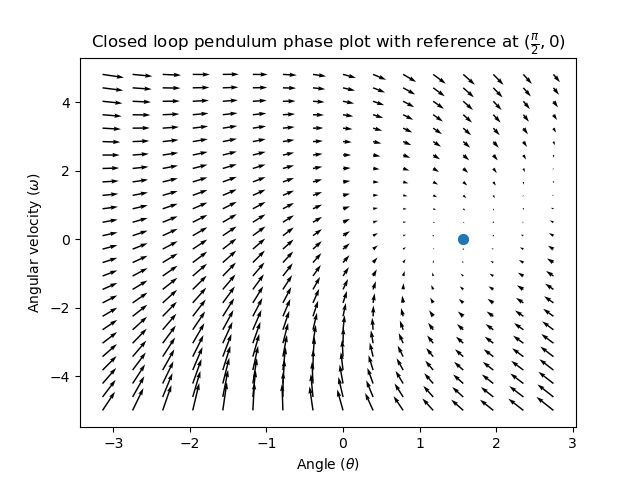
让我们举例说明这种控制律的实际作用。我们将从上方使用钟摆系统,其中摆动的钟摆环绕状态空间中的原点。:math:`mathbf{K}`是零矩阵(一个全为零的矩阵)的情况就像选择P和D增益为零-没有控制输入将被应用,并且相画像看起来与上面的相同。
要添加一些反馈,我们可以任意选择 \(\mathbf{K}\) [2, 2],其中摆的:term:input 是角加速度。这个K意味着对于每一个位置 error`弧度,角加速度是为2弧度每二次方秒;类似地,我们以2弧度每二次方秒的加速度对于每弧度每二次方秒的 :term:`error。尝试从状态空间中的某个地方向内跟随箭头-无论初始条件如何,状态将稳定在:term:reference,而不是用纯粹的前馈无休止地循环。
但是我们如何为我们的系统选择一个最优的:term:gain`矩阵K?虽然我们可以手动选择: :term:`gains 1 并模拟系统响应或像PID控制器一样在机器人上对其进行调整,但现代控制理论有一个更好的答案:线性二次调节器(LQR)。
线性二次调节器
因为基于模型的控制意味着我们可以在给定初始条件和未来控制输入的情况下预测系统的未来状态,所以我们可以选择数学上最优的:term:gain 矩阵:math:mathbf{K}。要做到这一点,我们首先必须定义“好”或“坏”的:math:mathbf{K} 会是什么样子。我们通过将误差平方和控制输入随时间的变化相加来做到这一点,这将给我们一个数字,表示我们的控制律有多“糟糕”。如果我们使这个和最小化,我们就得到了最优控制律。
LQR:定义
Linear-Quadratic Regulators work by finding a control law that minimizes the following cost function, which weights the sum of error and control effort over time, subject to the linear system dynamics \(\mathbf{x_{k+1} = Ax_k + Bu_k}\).
The control law that minimizes \(\mathbf{J}\) can be written as \(\mathbf{u = K(r_k - x_k)}\), where \(r_k - x_k\) is the error.
备注
LQR设计的 \(\mathbf{Q}\) 和 \(\mathbf{R}\) 矩阵不需要离散化,但是为连续时间和离散时间:term:systems 1 计算的 \(\mathbf{K}\) 将有所不同。
LQR: 调试
就像可以通过调节PID增益来调整PID控制器一样,我们也想改变控制律平衡误差和输入的方式。例如,一艘太空船可能希望将其消耗的燃料减至最小,以达到给定的参考值,而高速机械臂可能需要对干扰做出快速反应。
我们可以使用 \(\mathbf{Q}\) 和 \(\mathbf{R}\) 矩阵在LQR中加权错误并控制工作量。在我们的成本函数(描述了控制律将如何“糟糕”地执行)中, \(\mathbf{Q}\) 和 \(\mathbf{R}\) 分别权衡我们的误差和控制输入。在上面的飞船示例中,我们可以使用带有相对较小数字的:math:mathbf{Q} 来表明我们不想过度影响误差,而我们的 :math:`mathbf{R}`可能很大,表明燃料消耗是不可取的。
使用WPILib,LQR类可以获取所需的最大状态偏移和控制量的向量,并根据布赖森规则在内部将它们转换为完整的Q和R矩阵。我们经常使用小写的:math:mathbf{q} 和 \(\mathbf{r}`指代这些向量,使用:math:\)mathbf{Q}` 和 :math:`mathbf{R}`指代矩阵。
Increasing the \(\mathbf{q}\) elements would make the LQR less heavily weight large errors, and the resulting control law will behave more conservatively. This has a similar effect to penalizing control effort more heavily by decreasing \(\mathbf{r}\)'s elements.
Similarly, decreasing the \(\mathbf{q}\) elements would make the LQR penalize large errors more heavily, and the resulting control law will behave more aggressively. This has a similar effect to penalizing control effort less heavily by increasing \(\mathbf{r}\) elements.
例如,对于具有位置和速度状态的抬升系统,我们可以使用以下Q和R。
// Example system -- must be changed to match your robot.
LinearSystem<N2, N1, N1> elevatorSystem = LinearSystemId.identifyPositionSystem(5, 0.5);
LinearQuadraticRegulator<N2, N1, N1> controller = new LinearQuadraticRegulator(elevatorSystem,
      // q's elements
      VecBuilder.fill(0.02, 0.4),
      // r's elements
      VecBuilder.fill(12.0),
      // our dt
      0.020);
// Example system -- must be changed to match your robot.
   LinearSystem<2, 1, 1> elevatorSystem = frc::LinearSystemId::IdentifyVelocitySystem(5, 0.5);
   LinearQuadraticRegulator<2, 1> controller{
      elevatorSystem,
      // q's elements
      {0.02, 0.4},
      // r's elements
      {12.0},
      // our dt
      0.020_s};
from wpimath.controller import LinearQuadraticRegulator_2_1
from wpimath.system.plant import LinearSystemId


# Example system -- must be changed to match your robot.
elevatorSystem = LinearSystemId.identifyPositionSystemMeters(5, 0.5)
controller = LinearQuadraticRegulator_2_1(
   elevatorSystem,
   # q's elements
   (0.02, 0.4),
   # r's elements
   (12.0,),
   # our dt
   0.020,
)
LQR:示例应用
Let’s apply a Linear-Quadratic Regulator to a real-world example. Say we have a flywheel velocity system determined through system identification to have \(K_v = 1 \frac{\text{volts}}{\text{radian per second}}\) and \(K_a = 1.5 \frac{\text{volts}}{\text{radian per second squared}}\). Using the flywheel example above, we have the following linear system:
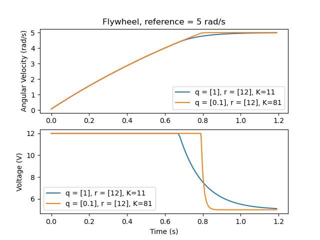
我们任意选择所需的状态偏移(最大误差):math:q = [0.1text{rad/sec}], \([12\ \text{volts}]`的 :math:\)mathbf{r}` 。在20ms的时间步长下离散化后,我们得到的:term:gain`为 :math:mathbf{K} = ~81`。这个:term:gain K作为PID回路对飞轮速度的比例分量。
Let’s adjust \(\mathbf{q}\) and \(\mathbf{r}\). We know that increasing the q elements or decreasing the \(\mathbf{r}\) elements we use to create \(\mathbf{Q}\) and \(\mathbf{R}\) would make our controller more heavily penalize control effort, analogous to trying to driving a car more conservatively to improve fuel economy. In fact, if we increase our error tolerance q from 0.1 to 1.0, our gain matrix \(\mathbf{K}\) drops from ~81 to ~11. Similarly, decreasing our maximum voltage \(r\) from 12.0 to 1.2 decreases \(\mathbf{K}\).
下图显示了飞轮的角速度和施加的电压随时间的变化,具有两个不同的 gain。我们可以看到更高的 :term:`gain`将如何使系统更快地到达参考点(t = 0.8秒时),同时使我们的电机在12V时保持更长时间的饱和状态。这与将PID控制器的P增益增加约8倍完全相同。
LQR和测量延迟补偿
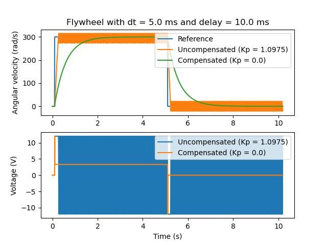
通常,我们的传感器会因测量而延迟。例如,通过CAN的SPARK MAX电动机控制器可能具有与速度测量相关的长达30ms的延迟。
这种滞后现象意味着我们的反馈控制器将基于过去的状态估计来生成电压命令。如下图所示,这通常会给我们的系统带来不稳定性和振荡。
However, we can model our controller to control where the system’s state is delayed into the future. This will reduce the LQR’s gain matrix \(\mathbf{K}\), trading off controller performance for stability. The below formula, which adjusts the gain matrix to account for delay, is also used in system identification.
Multiplying \(\mathbf{K}\) by \(\mathbf{A} - \mathbf{BK}\) essentially advances the gains by one timestep. In this case, we multiply by \(\left(\mathbf{A} - \mathbf{BK}\right)^{\text{delay} / dt}\) to advance the gains by measurement’s delay.
备注
这样可以将:math:`mathbf{K}`减小为零,从而有效地禁用反馈控制。
备注
SPARK Max电机控制器使用40抽头FIR滤波器,其延迟为19.5ms,默认情况下每20ms发送一次状态帧。
以下代码显示了如何针对传感器输入延迟来调整LQR控制器的K增益:
// Adjust our LQR's controller for 25 ms of sensor input delay. We
// provide the linear system, discretization timestep, and the sensor
// input delay as arguments.
controller.latencyCompensate(elevatorSystem, 0.02, 0.025);
// Adjust our LQR's controller for 25 ms of sensor input delay. We
// provide the linear system, discretization timestep, and the sensor
// input delay as arguments.
controller.LatencyCompensate(elevatorSystem, 20_ms, 25_ms);
# Adjust our LQR's controller for 25 ms of sensor input delay. We
# provide the linear system, discretization timestep, and the sensor
# input delay as arguments.
controller.latencyCompensate(elevatorSystem, 0.020, 0.025)
线性化
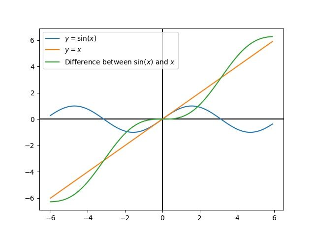
线性化是一种工具,用于近似非线性函数和状态空间系统的线性处理。在二维空间中,线性函数是直线,而非线性函数是曲线。一个常见的非线性函数及其对应的线性近似例子是 \(y=\sin{x}\), \(y=x\) 在0附近时,可以近似使用这个函数。当接近 \(x=0`时,这个近似是准确的,但随着我们离线性化点越来越远,该精度会降低。例如,在:math:`y = 0的0.5弧度内,近似值 :math:\)sin{x} approx x`精确到0.02以内,但是很快就失去了精度。在下面的图中,我们看到:math:y =sin{x}, \(y=x`以及 :math:`x`处 :math:\)sin{x}`的近似值和真实值之间的差值。
我们还可以使用非线性 dynamics`将状态空间系统线性化。为此,我们在状态空间中选择一个点 :math:mathbf{x}` 并将其用作非线性函数的输入。像上面的示例一样,这对于系统线性化的点附近的状态效果很好,但是可以迅速偏离该状态。