FRC Driver Station Powered by NI LabVIEW
Este artículo describe el uso y las características de FRC® Driver Station desarrollado por NI LabVIEW.
Para información sobre la instalación del software de la Driver Station vea este documento.
Empezar la FRC Driver Station
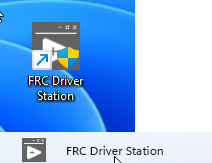
The FRC Driver Station can be launched by double-clicking the icon on the Desktop or by selecting Start->All Apps->FRC Driver Station.
Nota
By default the FRC Driver Station launches the LabVIEW Dashboard. It can also be configured on Setup Tab to launch the other Dashboards: SmartDashboard and Shuffleboard. WPILib must be installed to use SmartDashboard and Shuffleboard.
Atajos de teclado de la Driver Station
F1 - Force a Joystick refresh.
[ + ] + \ - Enable the robot (the 3 keys above Enter on most keyboards)
Enter - Disable the Robot
Space - Emergency Stop the robot. After an emergency stop is triggered the roboRIO will need to be rebooted before the robot can be enabled again.
Nota
La barra espaciadora detendrá al robot independientemente de si la ventana de la Driver Station está enfocado o no.
Advertencia
When connected to FMS in a match, teams must press the Team Station E-Stop button to emergency stop their robot as the DS enable/disable and E-Stop key shortcuts are ignored.
Configurar la FRC Driver Station

La DS debe configurarse con el número de su equipo para conectarse a su robot. Para hacer esto haga clic en la pestaña de Setup y luego ingrese su número de equipo en el cuadro de número de equipo. Presione return o haga clic fuera del cuadro para que la configuración tenga efecto.
PCs will typically have the correct network settings for the DS to connect to the robot already, but if not, make sure your Network adapter is set to DHCP.
Status Pane
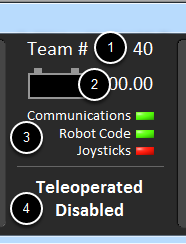
El Status Pane de la Driver Station está localizado en el centro del monitor y siempre está visible independientemente de la pestaña que esté seleccionada. Muestra una selección de información crítica sobre el estado de la DS y el robot:
Team # – El número del equipo para el cual el DS está configurado actualmente. Esto debería de coincidir con su número de equipo de FRC. Para cambiar el número de equipo vea la pestaña de Setup.
Battery Voltage – Si la DS está conectada y comunicándose con la roboRIO, esta muestra el voltaje de la batería actual como un número con una pequeña tabla del voltaje a lo largo del tiempo en el ícono de la batería. El fondo del indicador numérico se volverá rojo cuando se desencadene un apagón de la roboRIO. Vea Caída de voltaje en roboRIO y Comprender el Consumo de Corriente para más información.
Major Status Indicator – Estos tres indicadores muestran los principales elementos de estado para la DS. “Communications” indica cuando la DS está actualmente comunicándose con FRC Communications Task en la roboRIO (está dividido por la mitad para la comunicación de TCP y UDP). El indicador del código del robot muestra cuando el código del robot se está ejecutando actualmente (determinado cuando la Driver Station Task del código del robot está o no actualizando el voltaje de la batería), el indicador de los “joysticks” muestra si por lo menos alguno de los joysticks está conectado y reconocido por la DS.
Status String - The Status String provides an overall status message indicating the state of the robot. Some examples are «No Robot Communication», «No Robot Code», «Emergency Stopped», and «Teleoperated Enabled». When the roboRIO brownout is triggered this will display «Voltage Brownout».
Operation Tab

La Operation Tab es usada para controlar el modo del robot y proporcionar indicadores clave de estado adicionales mientras el robot está funcionando.
Robot Mode - This section controls the Robot Mode.
Teleoperated Mode causes the robot to run the code in the Teleoperated portion of the match.
Autonomous Mode causes the robot to run the code in the Autonomous portion of the match.
Practice Mode causes the robot to cycle through the same transitions as an FRC match after the Enable button is pressed (timing for practice mode can be found on the setup tab).
Test Mode is an additional mode where test code that doesn’t run in a regular match can be tested.
Enable/Disable - These controls enable and disable the robot. See also Driver Station Key Shortcuts.
Elapsed Time - Indicates the amount of time the robot has been enabled.
PC Battery - Indicates current state of DS PC battery and whether the PC is plugged in.
PC CPU% - Indicates the CPU Utilization of the DS PC.
Window Mode - When not on the Driver account on the Classmate allows the user to toggle between floating (arrow) and docked (rectangle).
Team Station – Cuando no esté conectada a FMS, configure la team station para transmitir al robot.
Nota
When connected to the Field Management System the controls in sections 1 and 2 will be replaced by the words FMS Connected and the control in Section 7 will be greyed out.
Diagnostics Tab
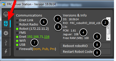
La Diagnostics Tab contiene indicadores de estado adicionales que los equipos pueden usar para diagnosticar los problemas con su robot:
DS Version - Indicates the Driver Station Version number.
roboRIO Image Version - String indicating the version of the roboRIO Image.
WPILib Version - String indicating the version of WPILib in use.
CAN Device Versions - String indicating the firmware version of devices connected to the CAN bus. These items may not be present if the CTRE Phoenix Framework has not been loaded.
Memory Stats - This section shows stats about the roboRIO memory.
Connection Indicators – La mitad superior de estos indicadores muestra el estado de conexión a varios componentes.
“Enet Link” indica que la computadora tiene algo conectado en el puerto de Ethernet.
“Robot Radio” indica el estado de ping al puente inalámbrico del robot en 10.XX.YY.1.
“Robot” indica el estado de Ping a la roboRIO utilizando mDNS (con un respaldo de dirección estática 10.TE.AM.2).
“FMS” indica si la DS está recibiendo paquetes de FMS (esto NO es un indicador de ping).
Network Indicators - The second section of indicators indicates status of network adapters and firewalls. These are provided for informational purposes; communication may be established even with one or more unlit indicators in this section.
“Enet” indica la dirección IP del adaptador de Ethernet detectado.
“WiFi” indica si un adaptador inalámbrico ha sido detectado como habilitado.
“USB” indica si una conexión USB de la roboRIO ha sido detectada.
«Firewall» indicates if any firewalls are detected as enabled. Enabled firewalls will show in orange (Dom = Domain, Pub = Public, Prv = Private)
Reboot roboRIO - This button attempts to perform a remote reboot of the roboRIO (after clicking through a confirmation dialog).
Restart Robot Code - This button attempts to restart the code running on the robot (but not restart the OS).
Setup Tab
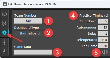
La Setup Tab contiene un número de botones los cuales el equipo puede utilizar para controlar la operación de la Driver Station:
Team Number - Should contain your FRC Team Number. This controls the mDNS name that the DS expects the robot to be at. Shift clicking on the dropdown arrow will show all roboRIO names detected on the network for troubleshooting purposes.
Dashboard Type - Controls what Dashboard is launched by the Driver Station. Default launches the file pointed to by the «FRC DS Data Storage.ini» (for more information about setting a custom dashboard). By default this is Dashboard.exe in the Program Files (x86)\FRC Dashboard folder. LabVIEW attempts to launch a dashboard at the default location for a custom built LabVIEW dashboard, but will fall back to the default if no dashboard is found. SmartDashboard and Shuffleboard launch the respective dashboards included with the C++ and Java WPILib installation. Remote forwards LabVIEW dashboard data to the IP specified in Dashboard IP field.
Game Data - This box can be used for at home testing of the Game Data API. Text entered into this box will appear in the Game Data API on the Robot Side. When connected to FMS, this data will be populated by the field automatically.
Practice Mode Timing – Estas cajas controlan el tiempo de cada porción de la secuencia del modo de práctica. Cuando el robot está habilitado en modo de práctica la DS automáticamente avanza a través de los modos de indicados desde arriba hacia abajo.
Audio Control – Este botón controla si los tonos de audio suenan cuando se utiliza el modo de práctica.
USB Devices Tab
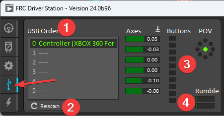
La USB Devices tab incluye la información sobre los dispositivos USB conectados a la DS
USB Setup List – Esta contiene una lista de todos los dispositivos USB compatibles conectados a la DS. Si presiona un botón en un dispositivo, resaltará el nombre del dispositivo en verde y pondrá 2 *s antes del nombre del dispositivo.
Rescan - This button will force a Rescan of the USB devices. While the robot is disabled, the DS will automatically scan for new devices and add them to the list. To force a complete re-scan or to re-scan while the robot is Enabled (such as when connected to FMS during a match) press F1 or use this button.
Device Indicators – Estos indicadores muestran el estado actual de Axes, botones y POV del joystick.
Rumble – Para dispositivos XInput (como controladores de X-Box) el control Rumble aparecerá. Este puede ser usado para probar la funcionalidad rumble del dispositivo. La barra superior es “Right Rumble” y la barra inferior es “Left Rumble”. Haciendo clic y manteniendo en cualquier lugar a lo largo de la barra, activará la proporcionalidad de Rumble ( izquierda es no rumble = 0 , derecha es rumble lleno = 1 ). Este es un control único y no indicará el valor de Rumble establecido en el código del robot.
Dispositivos de reordenamiento y bloqueo
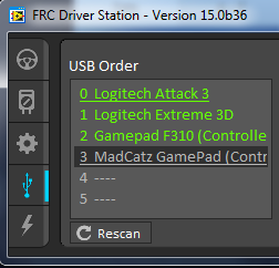
The Driver Station has the capability of «locking» a USB device into a specific slot. This is done automatically if the device is dragged to a new position and can also be triggered by double clicking on the device. «Locked» devices will show up with an underline under the device. A locked device will reserve its slot even when the device is not connected to the computer (shown as grayed out and underlined). Devices can be unlocked (and unconnected devices removed) by double clicking on the entry.
Nota
If you have two or more of the same device, they should maintain their position as long as all devices remain plugged into the computer in the same ports they were locked in. If you switch the ports of two identical devices the lock should follow the port, not the device. If you re-arrange the ports (take one device and plug it into a new port instead of swapping) the behavior is not determinate (the devices may swap slots). If you unplug one or more of the set of devices, the positions of the others may move; they should return to the proper locked slots when all devices are reconnected.
Ejemplo: la imagen de arriba muestra 4 dispositivos:
Un joystick “Logitech Attack 3” bloqueado. Este dispositivo se quedará en esta posición a menos de que sea arrastrada a otro lugar o desbloqueado.
Un joystick “Logitech Extreme 3D” desbloqueado.
Un “Gamepad F310 (Controller)” desbloqueado, el cual es un gamepad Logitech F310.
Un “MadCatz GamePad (Controller)” que está bloqueado, pero desconectado, el cual es un MadCatz Xbox 360 Controller.
En este ejemplo, si desconecta el joystick Logitech Extreme 3D resultará que el F310 Gamepad se moverá a la ranura 1. Conectar el MadCatz Gamepad (aunque los dispositivos en las ranuras 1 y 2 sean removidos y esas ranuras estén vacías) resultará en que este ocupe la ranura 3.
CAN/Power Tab
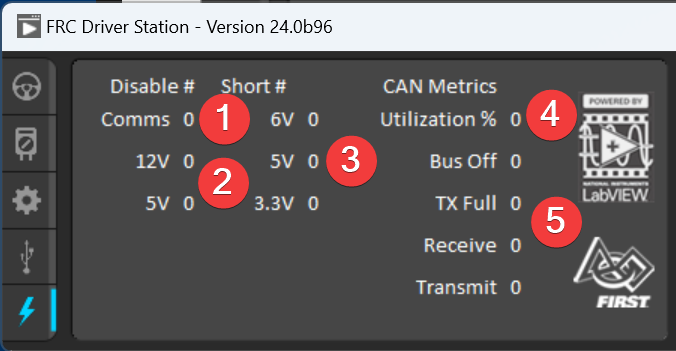
La última pestaña del lado izquierdo de la DS es la CAN/Robot Power Tab. Esta pestaña contiene información sobre el estado de energía de la roboRIO y el estado del CAN bus:
Comms Faults – Indica el número de falla de comunicaciones desde que la DS ha estado conectada.
12V Faults – Indica el número de fallas de alimentación de entrada (Brownouts) que han ocurrido desde que la DS ha estado conectada.
6V/5V/3.3V Faults - Indicates the number of faults (typically caused by short circuits) that have occurred on the User Voltage Rails since the DS has been connected
CAN Bus Utilization – Indica el porcentaje de utilización del CAN bus.
CAN faults – Indica los recuentos de cada uno de los 4 tipos de fallas de CAN desde que la DS ha estado conectada.
Si una falla es detectada, el indicador de esta pestaña (mostrado en azul en la imagen de arriba) se volverá roja.
Messages Tab
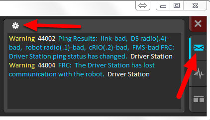
The Messages tab displays diagnostic messages from the DS, WPILib, User Code, and/or the roboRIO.
To access settings for the Messages tab, click the Gear icon. This will display a menu that will allow you to clear the box, launch a larger Console window for viewing messages, launch the DS Log Viewer, launch a viewer for program timing, or download log files from the robot.
Charts Tab
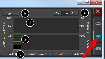
La Charts tab traza y muestra indicadores avanzados del estado del robot para ayudar a los equipos a diagnosticar los problemas del robot:
The top graph charts trip time in milliseconds in green (against the axis on the right) and lost packets per second in orange (against the axis on the left).
La gráfica inferior traza el voltaje de la batería en amarillo (contra el eje a la izquierda), roboRIO CPU en rojo (contra el eje de la derecha), el DS Requested Mode como una línea continua en el fondo de las gráficas y el robot mode como una línea discontinua arriba de esta.
Esta clave muestra los colores usados para la DS Requested y Robot Reported modes en la tabla inferior.
Chart scale - These controls change the time scale of the DS Charts.
This button launches the DS Log File Viewer.
El DS Requested mode es el modo en el que la Driver Station le ordena al robot que esté dentro. El Robot Reported mode es que código es el que se está ejecutando actualmente, basado en los métodos de informes contenidos en los marcos de codificación para cada lenguaje.
Both Tab
The last tab on the right side is the Both tab which displays Messages and Charts side by side.