Control System Basics
Note
This article is taken out of Controls Engineering in FRC by Tyler Veness with permission.
Control systems are all around us and we interact with them daily. A small list of ones you may have seen includes heaters and air conditioners with thermostats, cruise control and the anti-lock braking system (ABS) on automobiles, and fan speed modulation on modern laptops. Control systems monitor or control the behavior of systems like these and may consist of humans controlling them directly (manual control), or of only machines (automatic control).
How can we prove closed-loop controllers on an autonomous car, for example, will behave safely and meet the desired performance specifications in the presence of uncertainty? Control theory is an application of algebra and geometry used to analyze and predict the behavior of systems, make them respond how we want them to, and make them robust to disturbances and uncertainty.
Controls engineering is, put simply, the engineering process applied to control theory. As such, it’s more than just applied math. While control theory has some beautiful math behind it, controls engineering is an engineering discipline like any other that is filled with trade-offs. The solutions control theory gives should always be sanity checked and informed by our performance specifications. We don’t need to be perfect; we just need to be good enough to meet our specifications.
Nomenclature
Most resources for advanced engineering topics assume a level of knowledge well above that which is necessary. Part of the problem is the use of jargon. While it efficiently communicates ideas to those within the field, new people who aren’t familiar with it are lost.
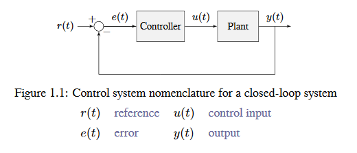
The system or collection of actuators being controlled by a control system is called the plant. A controller is used to drive the plant from its current state to some desired state (the reference). Controllers which don’t include information measured from the plant’s output are called open-loop controllers.
Controllers which incorporate information fed back from the plant’s output are called closed-loop controllers or feedback controllers.

Note
The input and output of a system are defined from the plant’s point of view. The negative feedback controller shown is driving the difference between the reference and output, also known as the error, to zero.
What is Gain?
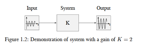
Gain is a proportional value that shows the relationship between the magnitude of an input signal to the magnitude of an output signal at steady-state. Many systems contain a method by which the gain can be altered, providing more or less “power” to the system.
The figure below shows a system with a hypothetical input and output. Since the output is twice the amplitude of the input, the system has a gain of two.

Block Diagrams
When designing or analyzing a control system, it is useful to model it graphically. Block diagrams are used for this purpose. They can be manipulated and simplified systematically.

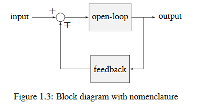
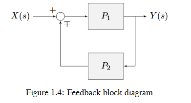
The open-loop gain is the total gain from the sum node at the input (the circle) to the output branch. this would be the system’s gain if the feedback loop was disconnected. The feedback gain is the total gain from the output back to the input sum node. A sum node’s output is the sum of its inputs.
The below figure is a block diagram with more formal notation in a feedback configuration.

\(\mp\) means “minus or plus” where a minus represents negative feedback.
Why Feedback Control?
Let’s say we are controlling a DC brushed motor. With just a mathematical model and knowledge of all the current states of the system (i.e., angular velocity), we can predict all future states given the future voltage inputs. Why then do we need feedback control? If the system is disturbed in any way that isn’t modeled by our equations, like a load was applied, or voltage sag in the rest of the circuit caused the commanded voltage to not match the applied voltage, the angular velocity of the motor will deviate from the model over time.
To combat this, we can take measurements of the system and the environment to detect this deviation and account for it. For example, we could measure the current position and estimate an angular velocity from it. We can then give the motor corrective commands as well as steer our model back to reality. This feedback allows us to account for uncertainty and be robust to it.